Bridge Alignment Dialog Box
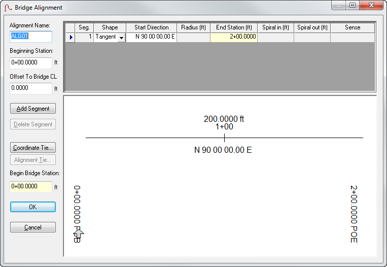
The Bridge Alignment dialog box allows you to define a bridge’s alignment by creating, modifying or deleting alignment tangents and/or curve segments.
To open this dialog box, click the Alignment button on the Geometry tab. LEAP Bridge Concrete allows the user to input bridge geometry directly from the plans. The program uses the actual layout geometrics to assist the user in defining the analysis model. The designer must determine appropriate span lengths for the analysis. When bridges are on roadway curves and/or include skewed supports, the distance between supports can vary, thus making the analysis model difficult to define. LEAP Bridge Concrete assists the designer by computing the distances between supports along the center line of the bridge. By default, LEAP Bridge Concrete creates a straight alignment along a N 90 E bearing. When a segment is created, deleted, or modified, all ahead-station segments in the bridge layout line automatically adjust themselves, thus maintaining individual segment lengths and angles relative to their back-station neighbor.
Adding Tangents
This function adds a straight segment to the bridge alignment after the selected segment. The new segment is tangent to and equal in length to the preceding alignment segment.
Adding Curves
This function adds a curved segment to the bridge alignment after the selected segment. The new segment is tangent and equal in length to the preceding alignment segment.
Deleting Segments
This function deletes a segment from the bridge layout line, and adjusts the starting direction of the following segment to create the effect of having progressively shortened the length of the deleted segment to zero.
Creating Alignment Ties
LEAP Bridge Concrete can export/save plan view data to CAD formats. Users can choose to tie exported/saved data to the state plane coordinates by identifying a location along the alignment, and specifying an appropriate coordinate value by clicking the Alignment Tie button to open the Alignment Tie dialog box.
Definitions
| Setting | Description |
|---|---|
| Beginning Station | Define the beginning station of the bridge alignment. |
| Offset to Bridge CL | Define the lateral offset from the alignment to the center line of the bridge. |
| Segment | This non-editable field displays the segment number of the alignment. |
| Shape | This non-editable field lists whether the segment is a tangent or a curve. |
| Start Direction |
Enter the starting direction of the segment. By default, the starting direction is equal to the direction of the end of the preceding segment. |
| End Station | Enter the ending direction of the segment. |
| Radius | Enter the radius for a curve segment. |
| Sense | Select the curve sense (left or right) from the drop-down list. |